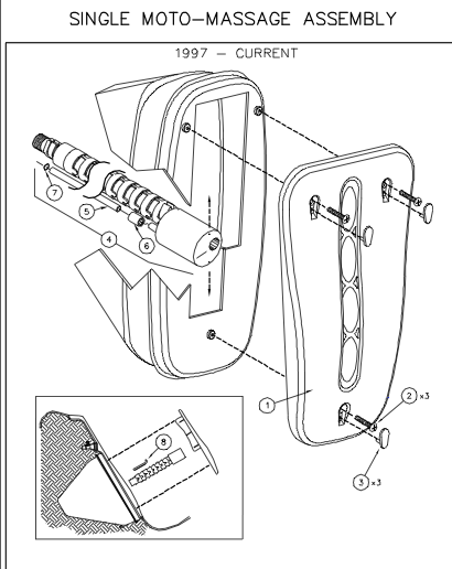
The Moto-Massage is a jet that automatically travels up and down to massage a person's back. The mixing of air and water in a jet, along with a playable spine causes the sweeping motion of the Moto-Massage. The intensity and speed of the Moto-Massage can be adjusted with the air control valve. The Moto-Massage is curved to fit the curvature of the back.
The Moto-Massage consists of a jet nozzle, water tube, threaded fitting, vertebra and an air tube with an o-ring. The Moto-Massage is held in place by a special recess behind the spa shell. A shim is used to assist in proper movement of the Moto-Massage.
Compatible with 2004 to 2008 Hot Spring Highlife spa models.
*Check specs section for full list of compatible models and years.
Using a standard blade screwdriver, remove the three faceplate screw covers.
Remove the three screws securing the Moto Massage faceplate to the spa.
Remove the Moto Massage faceplate.
Reach into the jet recess and locate the air tube. Gently remove this tube from the barbed nipple at the back of the recess.
Grasping the base of the Moto Massage (end closest to the rear of the jet recess) gently turn the entire assembly counterclockwise until it can be removed.
To reinstall the Moto Massage, reverse steps 1 to 6.
Important Instructions Regarding Moto Massage Alignment:
In order the for the Moto Massage to operate properly it is imperative that the Moto Massage nozzle be properly positioned after the assembly is tightened in the Moto niche.
To properly align, ensure that the two holes located on the nozzle face are position horizontally and that the Moto assembly travels vertically within the niche.
The following are the major causes of Moto-Massage failure;
Shim misaligned.
Low Water flow due to jet pump malfunction or dirty, clogged filters.
No or improper air mixture due to air valve failure, air line disconnected, frozen air lines, or non-operative check valves.
Using a standard blade screwdriver, remove the three faceplate screw covers.
Remove the three screws securing the Moto Massage faceplate to the spa.
Remove the Moto Massage faceplate.
Reach into the jet recess and locate the air tube. Gently remove this tube from the barbed nipple at the back of the recess.
Grasping the base of the Moto Massage (end closest to the rear of the jet recess) gently turn the entire assembly counterclockwise until it can be removed.
To reinstall the Moto Massage, reverse steps 1 to 6.
Important Instructions Regarding Moto Massage Alignment:
In order the for the Moto Massage to operate properly it is imperative that the Moto Massage nozzle be properly positioned after the assembly is tightened in the Moto niche.
To properly align, ensure that the two holes located on the nozzle face are position horizontally and that the Moto assembly travels vertically within the niche.
Item
Description
Part Number
1a
Facia Plate Moto White
36079
1b
Facia Plate Moto C Grey
36511
1c
Facia Plate Moto W Grey
73305
2
Screw 16x3
34366
3a
Screw Cover Moto White
36144
3b
Scrrew Cover Moto c grey
36510
3c
Screw Cover Moto w grey
73306
3d
Screw Cover Taupe
71896
4
Moto Jet Assembly white
73307
5
Air Tube with o oring
70307
6
Abraision cap (air tube)
30723
7
O ring moto air tube
33020
8a
Extrusion shim MM Short
36143
8b
Extrusion shim MM Long
36557
*
Check Valve
38390
* Non Illustrated Part
Removal
Open or remove the spa cover.
Using a standard blade screwdriver, remove the three faceplate screw covers.
Remove the three screws securing the Moto Massage faceplate to the spa.
Remove the Moto Massage faceplate.
Reach into the jet recess and locate the air tube. Gently remove this tube from the barbed nipple at the back of the recess.
Grasping the base of the Moto Massage (end closest to the rear of the jet recess) gently turn the entire assembly counterclockwise until it can be removed.
To reinstall the Moto Massage, reverse steps 1 to 6.
Important Instructions Regarding Moto Massage Alignment:
In order the for the Moto Massage to operate properly it is imperative that the Moto Massage nozzle be properly positioned after the assembly is tightened in the Moto niche.
To properly align, ensure that the two holes located on the nozzle face are position horizontally and that the Moto assembly travels vertically within the niche.