
In Stock
74380 Aux. Panel 2 Pump
$158.56
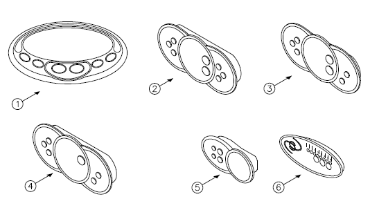
This part is a replacement aux. panel 2 pump for select Caldera hot tubs. The main display shows which spa functions are active (light, jets, locking features).The control head, located on the bar top, consists of an electronic board and housing with a conformal-coated moisture, resistant barrier. The control head serves as an interface between the control panel and the control box.
Usually Ships Within 2 Business Days
Buy with Confidence: 
Customers who bought this also bought


Product Description
Product Specifications
Questions